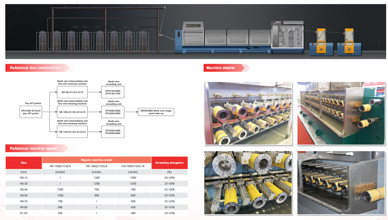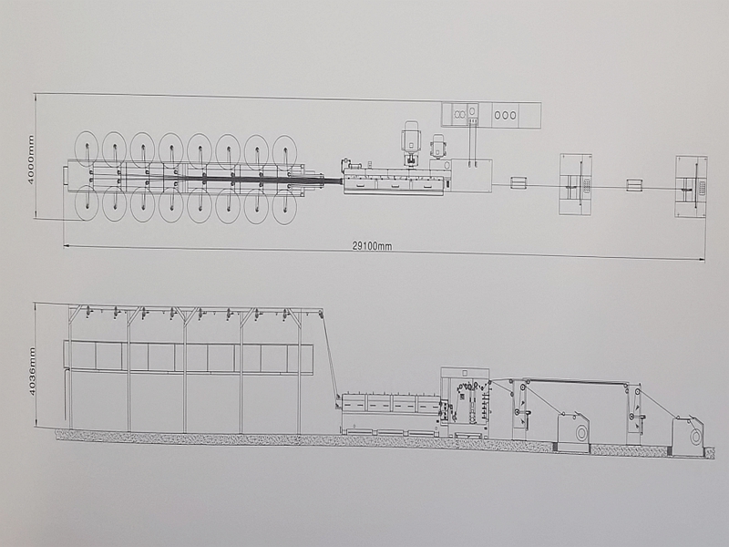


1.Main components of machine
|
No |
Machine’s name |
Qty |
|
1 |
16 wires pay off |
1 |
|
2 |
Multi wire drawing machine |
1 |
|
3 |
Online annealer |
1 |
|
4 |
Take up machine |
2 |
|
5 |
Cooling system of annealer shaft |
1 |
|
6 |
Electrical control cabinet |
1 |
2.Technical parameters
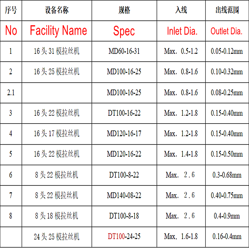
1.Inlet diameter : 16*Φ1.50mm ~ 1.80mm (250N/mm2)
2.Outlet diameter: 16*Φ0.10mm ~ 0.40mm
3.Number of produced wires: 16 x copper bare / copper tinned (2 Levels, with 16 wires)
4.Max.drawing speed: 1800m/min
5.Drawing passes: Max.25 .
6.Drawing rings: 100mm with 8 grooves . For separate and parallel wire guidance Material: zirconia.
7.Final drawing ring: 100mm 8 grooves. For separate and parallel wire guidance Material: zirconia
8.Drawing dies: φ max. 28mm x max. 12 mm thickness
9.Cooling water supply: Max. 25℃ inlet temperature;
10.Differential pressure between cooling water inlet and outlet is 2 bar (2 x 10^5 Pa)
11.Compressed air supply: 6 bar over pressure (7 x 10^5 Pa) , water- and oil free
12.Spool : PN 630
13.direction: from left to right
14.Colour: According to customer requirements
|
Wire Diameter. |
Line speed |
Elongation |
|
16*φ0.100mm |
at v =20.0m/s |
≥16% |
|
16*φ 0.150mm |
at v =22.0m/s |
≥18% |
|
16 *φ 0.180mm |
at v =23.0m/s |
≥20% |
|
16*φ 0.200mm |
at v =23.0m/s |
≥20% |
|
16 * φ 0.254mm |
at v =22.0m/s |
≥25% |
|
Production efficiency for tinned wires at production speeds reduced by about 20%. |
||
3. Equipment description
1.Quick die change system: Allows the production of various diameters without exchanging the complete die sets;
The rpm adjustment of the last capstan to the final capstan (necessary due to omission of one or several drawing steps) is pre-set by the 2-motor-technique in connection with free- programmable control (PLC).
2.Drive of annealer and contact pulleys: By endless flat belt in the annealer, drive directly from the drawing machine by flat belts; belt tension can be regulated via tension pulley.
3.Wire traverse mechanism:Driven by AC servo-motor;
a)Constant traverse speed:When in this mode, the traverse pitch changes with the filling degree of the spool, which means, the traverse pitch increase with the spool getting fuller. The filling weight is lower than with constant traverse pitch
b)Constant traverse pitch: The traverse speed will be adapted to the spool speed when in this mode.
The traverse pitch is kept constant during the complete winding process
Option: automatic adjustment of traverse width.
4.Machine specification
1.Pay-off
Structure: steel welding structure; pulleys; for 16 basket type
1.Multi-wire drawing machine
1.Construction: Multi-wire tandem drawing machine without wire deflections, drawing direction horizontal
2.Main drives: Compact high voltage variable frequency AC motor: For main machine:180KW 1 set; For haul-off capstan: 45KW 1 set; DC inverter: Siemens.
3.Auxiliary drives: Gear oi pump: about 4 KW, none stop oil supply; Capacity 600L/min
4.Drawing lubricant: About 300 l/min per level with 2.0 bar over pressure (3.0 x 10⁵ Pa); At 40℃ inlet temperature
5.Cooling water: Lubricant return cooling: About 7 m3/h (with self-contained supply) ; Gear oil return cooling:About 1.2 m3/h
6.Bearings: NSK+ SKF
7.Gearing: High efficiency spur gear, hardened and ground
8.Lubrication: Oil circulation type lubrication for toothed wheels and bearings
9.Lubricant system: Drawing capstans sprayed in the drawing area, drawing dies pressure-lubricated through die holders
3.Online annealer
1.Construction: DC continuous resistance annealer
2.Annealing principle: Two and Three-zone system (optional)
3.Annealer drive: Synchronously via flat/toothed belts
4.Annealing voltage: Max.60V, depending on max. Speed
5.Annealing current: Max.2000A-DC
6.Annealing power: Max.120KW
7.Contact pulleys: Φ140mm , with easily exchangeable nickel contact tubes.
8.Protection: Steam about 6kg/h at 0.3bar
Option: Nitrogen about 300l/h,max. permissible pressure reducing valve and a nitrogen monitoring.
9.Contact pulley bearing assemblies: Are designed as cartridge and installed electrically insulated in the annealer housing;
rolling bearings are lubricated for lifetime, no regreasing required.
10.Wire drying:Single wire drying, wire drier equipped with ceramic nozzles; Adjustable in 16 groups manually with valve
11.Coolant: Lower contact pulley sprayed; annealer base serves as coolant tank
12.Power supply: By a regulating transformer and rectifier, variable with wire program
13.Annealing voltage control: Automatically, depending on the wire speed; annealing
14.Cooling system of annealer shaft : volume 0.50 m3, 1m2 plate type heat exchanger works with pump 0.75KW, can cool the annealer shaft effectively.
The water should be treated without the calcium.
4. Single spooler
1.Spool dimensions: PND 630 mm Or according to customer bobbin size
2.Drive motor: AC 22kw
3.Drive: By motor, driving the spool shaft via flat belt.
4.Traverse drive: AC servomotor 1.5KW, 2000r/min
5.Spool take-up: bobbin hold by clamping cones, automatic spooling
6.Tension control: Pneumatic lever type; with line speed detective buffer pulley, winding speed auto adjusting.
7.Compressed air consumption: About 10 L/min
8.Brake: Disk brake with pneumatically actuated brake shoe ,serving only as quick brake
9.Braking time: Adjustable, max. 5 s in case of emergency-off
10.Spool loading and unloading: By means of spool carrier with pneumatic lifting table, operated manually.
11.Speed control: By dancer, spooler follows synchronously the speed of the drawing line and annealer
12.Control desk: Mounted at the side of the spooler
5.Electrical control system
1.Power supply
3-phase voltage ~3×380VAC (±10%)
Single-phase voltage ~220VAC (±10%)
Frequency 50Hz (±2%)
2.Switch cabinet
All facilities required for the control of the drawing, annealing etc. are installed in the switch cabinet.In addition, the control devices for driving and the linkage of all sets of the electrical equipment providing for the function of the whole line
3. Main electrical components:
|
12″ colour human machine interface(SIEMENS) |
1 set |
|
PLC(SIEMENS) |
1 set |
Drivers:
|
Drawing motor |
1 set |
|
capstan motor |
1 set |
|
Spooling motor |
2 sets |
|
Traversing servo motor |
1 set |
|
DC rectification power unit |
1 set |
|
Low-voltage electrical components <52A |
1 set |