|
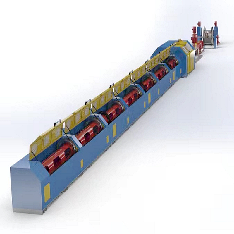
I. Main technical parameters |
|
|
Stranded material |
Steel wire, galvanized wire |
|
Maximum tensile strength of raw materials [MPa] |
2160 |
|
Wire strand diameter before twisting (mm) |
1.5-3.5 |
|
Strand diameter after twisting (mm) |
4.5-9.6 (conductor diameter13.5) |
|
Twist range (mm) |
40-102(Infinitely adjustable) |
|
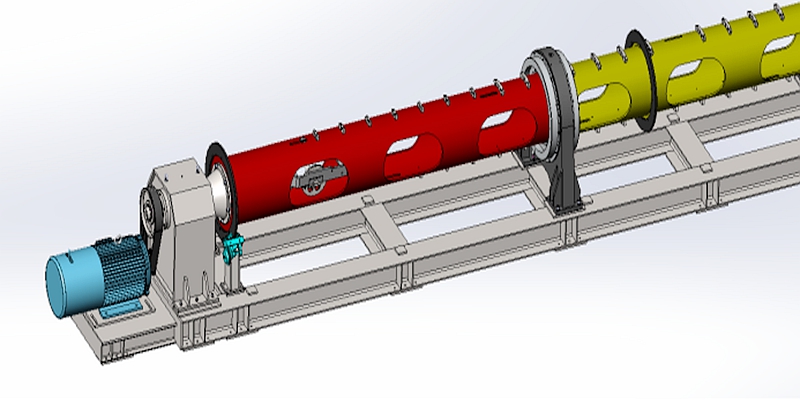
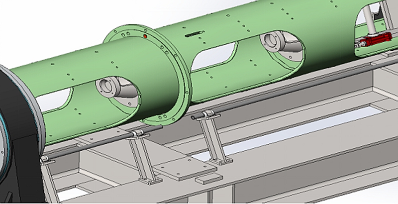
I-shaped wheel inside the cylinder |
Model 500(Party A provides drawings) |
|
Number of I-shaped wheels in the body |
6 |
|
Center wire pay-off I-shaped wheel |
500-1000(Party A provides drawings) |
|
Take-up I-shaped wheel (mm) |
800-1000(Party A provides drawings) |
|
Maximum working speed of cylinder design (r/min) |
650 |
|
Recommended operating speed [r/min] |
500 |
|
Main motor power (kw) |
37KW |
|
Main motor starting time |
less than 60 seconds |
|
Main motor pole number, control method |
4P, frequency conversion control |
|
Operation direction |
from left to right |
|
Pay-off tension control method |
Chain+friction block+spring |
|
Barrel material |
20 steel |
|
Cylinder threading method |
External threading |
|
Cylinder support method |
Large bearing support |
|
Large bearing lubrication and sealing |
Circulating thin oil lubrication, labyrinth seal, aluminum alloy oil slinger and oil retaining ring, good heat dissipation performance |
|
Large bearing accuracy |
P5 |
|
Large bearing seat material |
Ductile iron, good vibration damping |
|
Host base structure |
H-shaped steel is tailor-welded with sufficient rigidity. After welding, the internal stress is removed and annealed. Gantry milling is performed. The upper and lower sides are finely milled. |
|
Wire mold inner hole size (mm) |
Center stocks: Φ25 |
|
Outer winding strand: Φ15 |
|
|
Wire mold material |
YG8 |
|
cylinder brake |
It adopts pneumatic caliper brake, and each cylinder is equipped with a pair of brakes. The cylinder stops rotating in 3 to 5 seconds during emergency braking, and the brake is applied when power is lost. |
|
Brake disc material |
Nodular cast iron |
|
Offline parking protection function |
Use galvanized pipe to detect broken wires and stop the machine immediately if the broken wires |
|
Safety cover structure form |
Made of cold-rolled steel plate, fully enclosed design, sliding door structure or electric flipping |
|
Safety cover viewing window |
Using glass with bulletproof film |
|
Strand head Angle |
≤18º |
|
Distribution reel structure |
1+6 |
|
Stamping device |
Axially adjustable; die size: 120x60x(30+30)mm |
|
Die force |
Built-in compression spring, the pressing force can be adjusted manually |
|
Traction method |
Driven by a variable frequency motor, dual active traction wheels reduce slippage, and the traction wheels have double supports. |
|
Traction motor |
30Kw,4P |
|
Continuous stock function during power outage |
existence |
|
Traction wheel structure |
8 slots + 7 slots |
|
Traction wheel groove size (mm) |
Groove bottom diameter Φ1000;R10 |
|
Traction wheel material |
ZG340-640 |
|
Traction sheave groove hardness |
HRC50-55 |
|
Counting meters |
Mechanical + electrical dual meter counting |
|
Reserved installation length of rear deformer |
2.5 meters |
|
predeformer |
Party A brings its own |
|
Take-up machine |
Independent variable frequency motor drive, electric clamping, electric lifting |
|
Take-up motor |
15KW,4P |
|
Take-up tension control method |
Using torque control |
|
Arrangement form |
Ball screw cable arrangement, servo motor drive |
|
electric |
1. The operation panel has a human-machine interface display. The panel is equipped with functions such as running, stop, emergency stop, wire breakage, safety cover opening, speed display, lay length, and inverter failure. |
|
2. The take-up machine is equipped with start and stop buttons. |
|
|
3. A broken wire detection mushroom emergency stop button is installed in the car body, and the car body cover is equipped with an electronically controlled operating box equipped with start, stop, jog, and emergency stop buttons. |
|
|
2. Main accessories brands |
|
|
Big bearing brand |
Luoyang Huigong or Wafangdian Guangyang Bearing |
|
Main motor |
China brand Motor |
|
Frequency converter |
INVT |
|
PLC |
Siemens |
|
touchscreen |
Siemens |
|
Other electrical components |
Schneider, Chint |
|
Electric control cabinet |
One set of main electric control, the touch screen is installed on the electric control operating table |
|
3. Installation and debugging |
|
|
Anchor bolts |
Party B provides anchor bolts |
|
Power supply requirements |
Three-phase four-wire system 380V |
|
Air supply pressure |
Party A is responsible for connecting the compressed air to the equipment, with air pressure ≥0.5MPa |
|
Wire and Cable |
Party A is responsible for connecting the wires to the equipment control cabinet |
|
Installation and debugging |
Party B is responsible for installation and debugging, and Party A is responsible for foundation grouting and accommodation of installation and debugging personnel. Party B provides equipment foundation diagrams and a detailed list of wearing parts. |

![]()

HOOHA CO., LTD
Your reliable supplier of
Power cable making machine
LAN cable making machine
Optical fiber cable making machine